A highly interactive and highly effective approach to learning Engineering Statics.
Engineering Statics
$25
- Description
- Additional info for instructors
- What students will learn
- Learning objectives by module
- Course assessments, activities, and outline
- Other course details
- System requirements
- Included instructor tools
Description
Statics is the study of methods for quantifying the forces between bodies. Forces are responsible for maintaining balance and causing motion of bodies, or changes in their shape. Motion and changes in shape are critical to the functionality of artifacts in the man-made world and to phenomena in the natural world.
Statics is an essential prerequisite for many branches of engineering, such as mechanical, civil, aeronautical, and bioengineering, which address the various consequences of forces.
This Engineering Statics course contains many interactive elements, spread throughout, to promote conceptual understanding and problem solving skills. These include: simulations, some with adjustable paramet ers controlled by the student, to help visualize concepts; “walk-throughs” that integrate voice and graphics to explain an example of the procedure or a difficult concept; and, most prominently, interactive exercises in which students practice problem solving, while receiving hints and feedback.
High school physics, algebra, and trigonometry are recommended prerequisites. Engineering Statics uses algebra and trigonometry and is suitable for use with either calculus- or non-calculus-based academic statics courses. Completion of a beginning physics course is helpful for success in statics, but not required as all the key concepts are included in this course.
Topics Covered:
- Forces
- Free Body Diagrams
- Equilibrium of Simple Objects
- Machines and Structures Joined by Engineering Connections
- Trusses
- Friction
- Moments of Inertia
Changes in this Update Include:
- New module 15: Annotated Practice Problems – Machines.
Additional info for instructors
- Features of The Course
- Topics Covered and Their Sequence
- Additional Information for Instructors
1. FEATURES OF THE COURSE
The OLI Engineering Statics course consists of a series of units, each containing a set of modules. Each module is broken into a series of pages. Each page is devoted to a single carefully articulated learning objective that is independently assessed.
Since Statics is a subject that requires solving problems as well as understanding concepts, larger tasks have been carefully dissected, and addressed as individual procedural steps. To help students learn such procedures, we use several approaches.
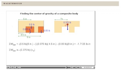
Walkthrough describing procedure of determining center of gravity for composite body.
First, we explain the procedure in straight text, often with a worked-out example. Second, we demonstrate the application of the procedure with a “Walkthrough” (an animation combining voice and evolving graphics that walks the student through an example of the procedure).
Students themselves first engage in problem solving procedures in “Learn By Doing” (LBD) exercises. These are computer-tutors in which students can practice the new skill as they receive detailed hints and feedback. Successive hints often have increasing degrees of specificity. Feedback for an incorrect answer may be generic (“That’s not right”) or specific and tailored to each incorrect answer, particularly when a likely diagnosis of the error can be made. There are over 300 such interactive exercises in the course; the following figure is an example using hints in a graphical and verbal form.
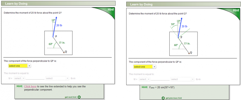
Learn By Doing on calculating moments using perpendicular and parallel components, illustrating hints in verbal and graphical form.
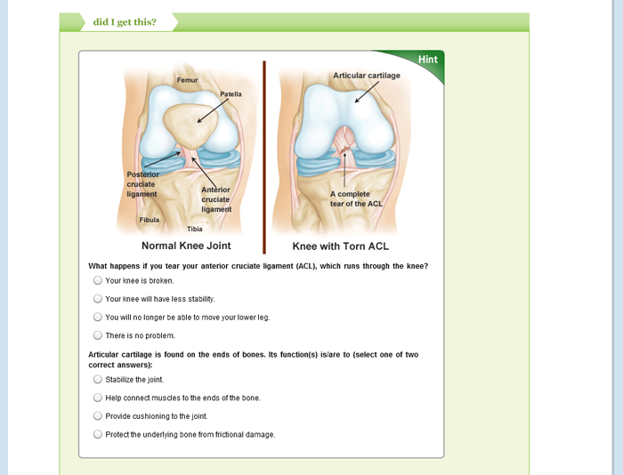
At the end of each page, students have another chance to see whether concepts were grasped and procedures mastered, through computer-tutors that are referred to as “Did I Get This?” (DIGT). Although they are similar in form, LBD tutors can be viewed as the learning activities, and DIGT tutors as self-assessment. Such assessments capture the goals of the learning objective. The following video illustrates using hints, feedback and scaffolding.
Example of a DIGT illustrating hints, feedback, and scaffolding.
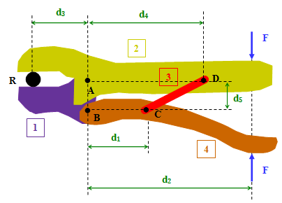
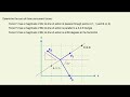
Here is another example of “Learn By Doing” in which students are to choose a subsystem to solve for a force at joint A in a cherry picker.
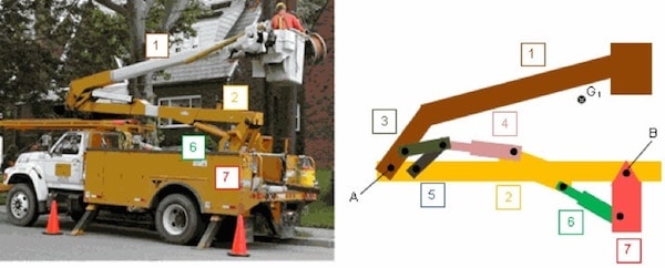
Example of a LBD illustrating hints, feedback, with graphical interface
In interactive guided simulations, students adjust parameters and see their effects (whit-if analysis). These are often initiated by a question that the student is supposed to answer. These simulations are also followed up with a succinct observation.
Example of guided simulation.
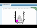
Also, consistent with the authors’ pedagogical philosophy of focusing initially on forces associated with manipulating simple objects, students are often guided to manipulate simple objects to uncover relevant lessons.
Example of use of digital images/manipulating simple objects.
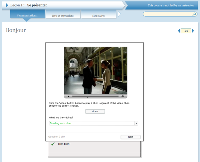
The course seeks to take advantage of digital images, video clips of relevant artifacts, and simulations of realistic mechanisms to the extent that they solidify ma terial presented and explain its range of application.
Example of use of video clips.
Example of use of simulations of mechanisms.
To help students review the key points, each page, which is devoted to a specific learning objective, ends with a brief summary called To Sum Up.
2. TOPICS COVERED AND THEIR SEQUENCE
OLI Engineering Statics covers the essential topics contained in most Statics textbooks (except it does not currently have 3-D statics or shear force and bending moment diagrams in beams).
The OLI Engineering Statics course takes a distinct approach to Statics in part through a reorganization of the order in which topics are presented. The authors believe a first exposure to equilibrium with a ttention to free body diagrams and the summation of forces and moments is valuable before the introduction of couples, static equivalence, and engineering connections.
The sequence of topics in OLI Statics is different from traditional textbooks only in the first two Units. But, the differences are easily manageable. To aid instructors and students who wish to use OLI in c onjunction with a traditional textbook, we have devised a mapping between OLI units and modules, and typical chapter/sections in textbooks.
3. ADDITIONAL INFORMATION FOR INSTRUCTORS
-
Learning Dashboard and Gradebook
- In academic sections of the course, besides providing students with real-time assessment and feedback by means of interactive exercises, the OLI Statics course gathers information on students’ on-line learning activities that instructors can use to inform classroom instruction. To provide instructors with such information the Learning Dashboard (LD) was developed.
The Learning Dashboard is an analytic system that uses a statistical model of students’ learning to analyze clickstream data in real time and provide useful and interpretable inferences, recommendations, and data visualizations for instructors. The Learning Dashboard helps instructors monitor students’ progress, identify students’ difficulties, and even “drill down” into the data to see students’ responses on individual problems. This information allows the instructor to pursue remedial instruction to address individual students’ needs and those shared by larger groups of students.
When instructors utilize the information to identify common student difficulties, classroom activities can be focused on specific concepts and skills that need elaboration and reinforcement. The image below shows the screenshot of the Learning Dashboard main page for Module 7 “Statically Equivalent Loads.” Based on an analysis of students’ performance on activities targeting a given learning objective, the system computes and displays graphically the Estimated Learning Levels for each of the learning objectives of the module. In particular, the proportion of the class at each learning level (red=low, yellow=moderate, green=high) is proportional to the respective portion of the bar, with gray representing students who have completed too few activities to enable a prediction.
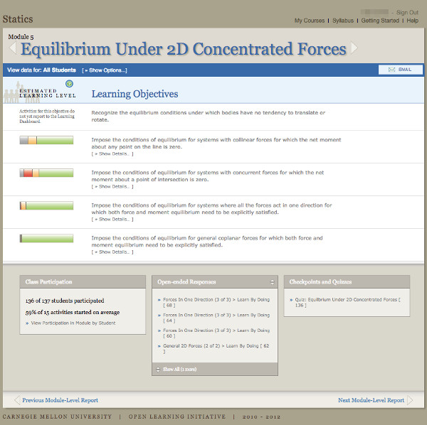
Screenshot of the main page of the OLI Engineering Statics Learning Dashboard.
To obtain more information about students’ progress and performance on a learning objective, the instructor clicks on that bar and the more detailed view shown below is revealed. Further clicking on the dots would show display the names of students in each of the above categories.
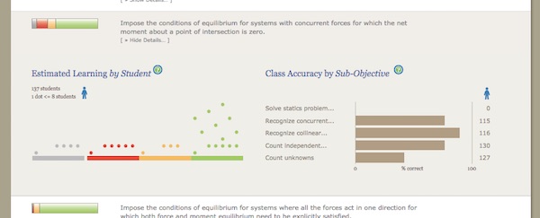
Screenshot of detailed information on Estimated Learning of one Learning Objective.
There are many other “hot links” on the bottom of the main LD page (Figure 3), each allowing the instructor to view different aspects of students’ activities and performance. In particular, at the bottom left of the LD main page is a link to a list of percentages of activities in the module in which each student engaged. The reports also quantify overall class use of interactive exercises aggregated across all students in the class. At the bottom in the middle of the LD main page is a link to My Response, where the instructor finds students’ written comments and questions as shown here.
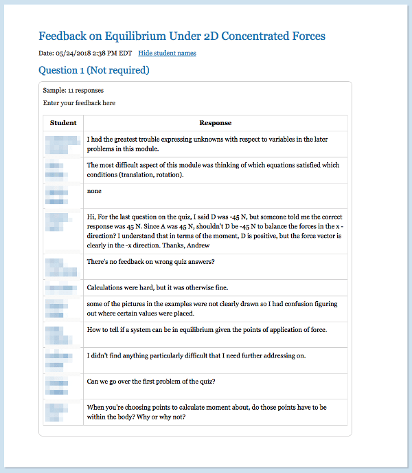
Excerpts from Module 5 My Response Report.
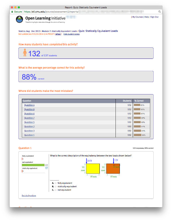
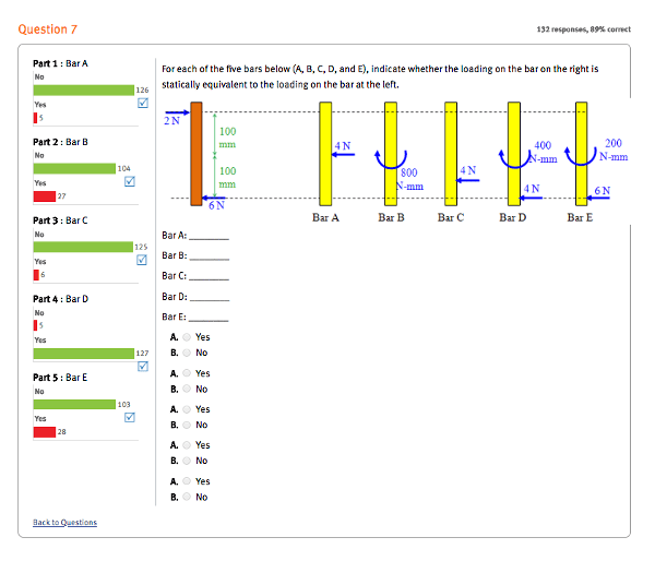
As a basis for a classroom discussion, an instructor may want to know how students answered individual questions, at least in an aggregate way. Learning Dashboard provides such feedback on virtually all inte ractive exercises. For example, excerpts from the Module 7 Quiz Report are shown in in the next two illustrations.
In summary the Learning Dashboard gives instructors a high-level overview of how students in a class are performing on the learning objectives for each module in the course. This gives instructors a rich view into what has always been a black box. Before going into class, instructors can quickly see the concepts students are grasping as well as the concepts with which students are struggling. This enables instr uctors to spend their time with students in a way that better utilizes their expertise.
The scores on end-of-module quizzes are reported to a Gradebook (can be exported as an excel file). Like other interactive exercises, the instructor can view performance on individual quiz questions and discuss them in class.
-
Inverted Classrooom Approach
- The authors of the OLI Engineering Statics course have used the OLI Engineering Statics course as part of their classroom-based Statics courses with lecture, optional textbook, and reduced written homework assignments. Our approach, which provides one possible approach for other instructors, is but one means of integrating OLI courseware. We call this approach the inverted classroom, because first contact with new material and formative assessments take place outside of the classroom, and students come to class prepared to be actively engaged.
- Prior to class, students are required to:
-
- complete selected OLI Statics modules with interactive exercises
- use the “My Response” link at the end of module to tell the instructor which concepts/ skills were the most difficult, and to ask questions they would like the instructor to address in class
- take the end-of-module quiz
- After students have completed OLI, but before class, instructor:
-
- reviews the Learning Dashboard (mastery of concepts and skills, quiz scores, “My Response” comments) and adjusts the classroom strategy “just in time”
- might email answers to some students’ “My response” questions or comments
- Class time is devoted to:
-
- reinforcement or more explanation of specific topics, concepts, and skills that were judged to require extra attention based on input from Learning Dashboard
- whatever else instructor views appropriate: solving problems, think-pair-share exercises, interesting applications, more advanced topics
-
Detailed Overview of The Units/Modules
-
Overview of the Course
In brief, the order of OLI Engineering Statics is to treat 2-D statics with simple forces (weight, normal force, cord, spring) first, without couples or engineering joints. Then, couples and static equivalence are covered, followed by engineering joints. More complex engineering statics problems, including two dimensional single body problems with engineering connections and multi-body problems follow the usual textbook sequence.
- Unit 1 (Modules 1 — 5)
- Forces, free body diagrams, moment due to a force, and then equilibrium for bodies under action of simple concentrated forces (no couples, distributed loads, or engineering connections). The authors believe a first exposure to equilibrium with attention to free body diagrams and the summation of forces and moments is valuable before introducing the couple , static equivalence, and engineering connections. In any event, we think the couple and static equivalence are far easier to understand if the concept of equilibrium is handled first.
Overview of Module 1
Overview of Module 2

Overview of Module 3
Overview of Module 4

Overview of Module 5
- Unit 2 (Modules 6 — 9)
- Couples (torques), distributed loads, static equivalence and modeling of engineering connections.

Overview of Unit 2
- Units 3 — 7 (Modules 10 — 20)
- Equilibrium of bodies with engineering connections (separated into free body diagrams, equilibrium conditions, and strategies for choosing subsystems to isolate). The remaining units cover frames and machines, trusses, friction, and moments of inertia.
Overview of Units 3-7
What students will learn
Topics Covered:
- Forces
- Free Body Diagrams
- Equilibrium of Simple Objects
- Machines and Structures Joined by Engineering Connections
- Trusses
- Friction
- Moments of Inertia
Learning objectives by module
Unit 1: Concentrated Forces and Their Effects
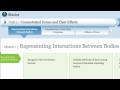
- Module 1: Representing Interactions Between Bodies
- Draw force vectors on bodies to reflect their attributes.
- Identify attributes of forces acting between a body and an attached cable.
- Identify attributes of forces acting between a body and an attached spring.
- Identify attributes of forces acting between frictionless contacting bodies.
- Recognize when two bodies interact.
- Module 2: Introduction to Free Body Diagrams
- Draw simple FBDs.
- Explain the purpose of drawing FBDs.
- Module 3: Effects of Force
- Define the tendency of the force to create rotation as the moment, and quantify the effect of the force magnitude, direction, sense and position on the moment.
- Determine the moment of a force by identifying the moment arm (perpendicular distance from the moment center).
- Distinguish between various motions produced by forces on bodies: translation, rotation with clockwise or counter-clockwise direction, and general motion.
- Recognize the roles of force magnitude, direction, sense, and line of action on the tendencies to cause translation and rotation motions.
- Module 4: Effects of Multiple Forces
- Add moments due to known forces when their moment arms are given.
- Determine the components of force vectors.
- Determine the moment of a force as a sum of the moments of its components parallel and perpendicular to the line between the moment center and the point of application of the force.
- Determine the moment of a force as a sum of the moments of its vertical and horizontal components.
- Determine the sum of concurrent forces by summing their components.
- Find the force magnitude and sense that balances the moment created by other forces.
- Judiciously choose method of calculating the moment of a force.
- Recognize that rotational effects of forces combine through the addition of moments.
- Recognize that translational effects of forces combine as in vector addition.
- Module 5: Equilibrium Under 2D Concentrated Forces
- Impose the conditions of equilibrium for general coplanar forces for which both force and moment equilibrium need to be explicitly satisfied.
- Impose the conditions of equilibrium for systems where all the forces act in one direction for which both force and moment equilibrium need to be explicitly satisfied.
- Impose the conditions of equilibrium for systems with collinear forces for which the net moment about any point on the line is zero.
- Impose the conditions of equilibrium for systems with concurrent forces for which the net moment about a point of intersection is zero.
- Recognize the equilibrium conditions under which bodies have no tendency to translate or rotate.
Unit 2: Complex Interactions Between Bodies
- Module 6: Couples
- Determine the moment of the couple from the forces producing it or balancing it, and recognize that a set of forces that can be represented as couples produces the same net moment about all points regardless of where they are applied.
- Recognize circumstances in which a multi-force interaction between two bodies can be represented as a couple, and determine the moment of the couple from what the couple interaction is balancing.
- Recognize that at least two forces are necessary to cause only a rotation of a body, and utilize the concept of a couple and its symbol to represent combinations of forces that produce zero net force (only a tendency to rotate).
- Module 7: Statically Equivalent Loads
- Distinguish between fully equivalent loadings and statically equivalent loadings.
- Recognize equivalence between: a) forces acting along the same line of action, b) several forces acting at a point and a single force at that point equal to their vector sum – full equivalence, and c) different combinations of forces that produce zero net force and the same total moment – equivalent couples.
- Replace a general set of forces and couples with a force and couple at a given point.
- Replace a general set of forces and couples with a single force at a location that needs to be determined.
- Replace a single force acting at a point with a statically equivalent force at a different point and an appropriate couple for the following situations: a) moving a force perpendicular to its line of action, and b) moving a force to an arbitrary location.
- Replace two parallel forces acting in the same direction and opposite senses with a statically equivalent load (force and couple).
- Replace two parallel forces acting in the same direction and sense with a single force.
- Module 8: Applications of Static Equivalency to Distributed Forces
- Determine the location of the center of gravity for bodies that can be decomposed into rectangular prisms.
- Recognize the role of symmetry planes in determining the location of the center of gravity.
- Replace a simple known distributed load by a single force with an appropriate line of action.
- Replace symmetrically distributed load per volume/area by a distributed load per length.
- Represent unknown distributed forces due to contact between symmetrical flat bodies by a statically equivalent force acting at an unknown location somewhere in the contact area.
- Use symmetry to reduce three-dimensional situations to two-dimensional representations.
- Use tabulated results to determine the location of the center of gravity for bodies that can be decomposed into simple shapes (and recognize that the location of the center of gravity for prismatic bodies can be determined by integration).
- Module 9: Representing Engineering Connections
- Recognize pin connections that can be modeled in 2-D even though forces act in different planes in 3-D: (a) symmetrical arrangements under symmetrical or planar loadings, (b) thin connected bodies under planar loadings.
- Recognize two most common connections: fixed and pinned.
- Represent interaction between bodies connected by a rigid sliding joint.
- Represent interaction between bodies connected by a shared pin (roles of Newton’s 3rd law and equilibrium).
- Represent interactions between a cylindrical rod and contacting surfaces common in connections.
- Represent interactions between bodies connected by a cable and a mass less pulley.
- Represent interactions between bodies connected by a link with two pins.
- Represent interactions between bodies connected by rollers, rockers, and pins in slot.
- Represent interactions between bodies joined by fixed connections.
Unit 3: Engineering Systems – Single Body Equilibrium
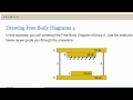
- Module 10: Drawing FBDs of a Single Subsystem
- For an identified subsystem, which is part of a larger system with engineering connections, represent all interactions with external parts on a FBD labeling all their known and unknown attributes.
- Module 11: Equilibrium of a Single Subsystem
- Account properly for forces and couples in equilibrium equations, and deduce their actual senses given their signs found from equilibrium and their assumed senses.
- Account properly for pre-modeled known distributed force described as q(x).
- Account properly for unknown distributed contact forces, and interpret the results of solution by recognizing physically impossible outcomes.
- Find the range of a parameter that ensures equilibrium, or the configuration that minimizes or maximizes a force.
- Use equilibrium conditions in a qualitative way, without actually solving them, to: make informed assumptions about senses of unknowns, or to recognize arrangements incapable of being in equilibrium, or to check the correctness of the senses of forces determined from the solution.
- Module 12: Choosing a Solvable Subsystem
- Choose solvable subsystems by recognizing two-force members when present.
- Choose solvable subsystems for simple systems (without engineering connections).
- Choose solvable subsystems for systems with engineering connections.
- Choose solvable subsystems for systems with pulleys.
Unit 4: Frames and Machines
- Module 13: Drawing FBDs of Multiple Subsystems
- Represent all interactions with external parts on FBDs of identified subsystems that are parts of a larger system, indicating all their known and unknown attributes, and obeying Newton’s 3rd law.
- Module 14: Solving Multiple Subsystems
- For systems with no fully solvable subsystems, identify partially solvable subsystem(s) (or the whole system) and solve subsystems using “back-and-forth” approach (some unknowns in one subsystem, then move to next).
- Identify a sequence of fully solvable subsystems (step 3) and solve for all unknowns in each subsystem by imposing successive equilibrium equations, each containing one unknown (step 4).
- Module 15: Annotated Practice Problems – Machines
- Solve complete multi-body statics problems by applying the four Steps of Statics studied in previous modules.
Unit 5: Trusses
- Module 16: Method of Joints
- Determine forces in bars connected to a single solvable joint.
- Select a sequentially solvable series of joints that allows all forces in truss members to be determined.
- Module 17: Method of Sections
- Determine internal forces in bars for a given section.
- Select subsystems that allow for an efficient solution for the desired forces.
Unit 6: Friction
- Module 18: Friction
- Determine conditions (load/geometry/friction coefficient) for which motion initiates or is sustained.
- Given the load, geometry and friction coefficient, determine if the body is stationary or slips.
- Recognize that the force between contacting bodies may have a normal and a tangential component. Define friction force, its limits and friction coefficients.
- Recognize that two contacting bodies may remain in contact, slip with respect to one another, or tip. Determine conditions for motion to initiate, and the type of impending motion.
Unit 7: Moments of Inertia
- Module 19: Second Moment of Area
- Define polar moment of area and recognize circumstances when it matters.
- Recognize second moment of area as a property relevant when the distribution of area is important rather than merely the area itself, and define second moment of an area.
- Use parallel axis theorem to find second moments of area about an arbitrary axis.
- Use tabulated results to determine second moment of area for simple shapes, including composite bodies with common centroidal axis.
- Module 20: Mass Moment of Inertia
- Recognize that distribution of mass, rather than mass alone, affects resistance to rotational motion, and define mass moment of inertia as measure of resistance to changes in its angular motion.
- Understand mass radius of gyration as an alternative measure of the resistance to rotation, which replaces an object of complicated shape with an equivalent ring (with same mass moment of inertia).
- Use parallel axis theorem to find mass moments of inertia about an arbitrary axis.
- Use tabulated results to determine mass moment of inertia for simple shapes, including composite bodies with common centroidal axis.
Course assessments, activities, and outline
How to use this course
What is Statics?
UNIT 1: Concentrated Forces and Their Effects
Module 1: Representing Interactions Between Bodies
Quiz: Representing Interactions Between Bodies
Module 2: Introduction to Free Body Diagrams
Quiz: Introduction to Free Body Diagrams
Module 3: Effects of Force
Quiz: Effects of Force
Module 4: Effects of Multiple Forces
Quiz: Effects of Multiple Forces
Module 5: Equilibrium Under 2D Concentrated Forces
Quiz: Applying Force Equilibrium
Quiz: Applying Force and Moment Equilibrium
UNIT 2: Complex Interactions Between Bodies
Module 6: Couples
Quiz: Couples
Module 7: Statically Equivalent Loads
Quiz: Statically Equivalent Loads
Module 8: Applications of Static Equivalency to Distributed Forces
Quiz: Simplifying 3D Loadings
Quiz: Center of Gravity and Centroid
Module 9: Representing Engineering Connections
Quiz: Representing Engineering Connections
UNIT 3: Engineering Systems – Single Body Equilibrium
Module 10: Drawing FBDs of a Single Subsystem
Quiz: Drawing FBDs of a Single Subsystem
Module 11: Equilibrium of a Single Subsystem
Quiz: Equilibrium of a Single Subsystem
Module 12: Choosing a Solvable Subsystem
Quiz: Choosing a Solvable Subsystem
UNIT 4: Frames and Machines
Module 13: Drawing FBDs of Multiple Subsystems
Quiz: Drawing FBDs of Multiple Subsystems
Module 14: Solving Multiple Subsystems
Quiz: Solving Multiple Subsystems
Module 15: Annotated Practice Problems – Machines
UNIT 5: Trusses
Module 16: Method of Joints
Quiz: Method of Joints
Module 17: Method of Sections
Quiz: Method of Sections
UNIT 6: Friction
Module 18: Friction
Quiz: Friction
UNIT 7: Moments of Inertia
Module 19: Second Moment of Area
Quiz: Second Moment of Area
Module 20: Mass Moment of Inertia
Quiz: Mass Moment of Inertia
Other course details
Approximately 3 hours per module for a total of approximately 60 hours.
December, 2013.
Coming soon.

This work is licensed under a Creative Commons Attribution-NonCommercial-ShareAlike 4.0 International License.
System requirements
OLI system requirements, regardless of course:
- internet access
- an operating system that supports the latest browser update
- the latest browser update (Chrome recommended; Firefox, Safari supported; Edge and Internet Explorer are supported but not recommended)
- pop-ups enabled
- cookies enabled
Some courses include exercises with exceptions to these requirements, such as technology that cannot be used on mobile devices.
This course’s system requirements:
- none listed (subject to change)
Cost and payment options
$25 per student
Students are prompted for payment during the OLI course registration process, and can pay with a credit card or an OLI Payment Code purchased from your campus bookstore.

Bulk discounts and alternative payment arrangements are available, including institutional or departmental payments. Learn about discounts and payment options.
Included instructor tools
Instructors who teach with OLI courses benefit from a suite of free tools, technologies, and pedagogical approaches. Together they equip teachers with insights into real-time student learning states; they provide more effective instruction in less time; and they’ve been proven to boost student success.
If you’d like to update an OLI course for your students, or even develop a new course or program of study, contact OLI Support for information about the OLI Author platform.
Learning and participation data is displayed in the Learning Dashboard. Read more.

Learning Engineering is the virtuous cycle of iterative improvement of learning content, instructional technologies, and the greater scientific research community. Read more
OLI courses can be deployed with preferences in dozens of areas, including: